
This is a tutorial for SMT 1.5mm dual LED backlights. Kits can be found here. The finished product can be found here.
Click the images to zoom in for a larger image.
This tutorial assumes you already know how to open your Game Boy, remove the screws holding in the front printed circuit board, and remove the circuit board from the case.
Please read through the whole tutorial before doing this. Everything is done sequentially and in a step-by-step order, but certain steps are reliant on others. If you don't read through beforehand you may end up with an unusable backlight!
Although this tutorial is designed for LED type backlight modules, many of these techniques can be applied to different backlighting technologies, such as EL panels. If you are using a different light source, feel free to interpret this tutorial a bit more loosely.
Parts List:
Wire cutters. A small pair will work better than a large pair, as you'll be snipping off component legs underneath your LCD.
Soldering iron
Solder
Hot glue gun
Razor blade
Tri Wing screwdriver
Small phillips head and flat-headed screwdrivers. A jeweler's set is a great investment for modding.
Resistor. A 1/4 Watt 100 ohm is perfect for these backlight modules. if you are doing you own thing you will need to calculate your own resistances.
Backlight module (or other means of lighting if you are doing your own thing)
Once you have your front PCB (printed circuit board) ready, remove the two screws holding the lower ribbon cable in place:

Carefully pry up the screen by inserting a small flat-headed screwdriver into the notch between the LCD (liquid crystal display) and plastic housing.

Remove the foam inserts. Now, depending on how you want to go about this next step, you will either be removing the reflective film on the back on the LCD or both the film and the rear polarized film. I highly recommend removing both and replacing the rear polarized film with a new one, as it's both easier to remove and generally results in a better looking LCD at the end due to all adhesive layers being removed. If you only remove the reflective film, there will still be an exposed layer of adhesive on the rear polarized film which will get progressively dirtier as you proceed. Additionally, if you end up having to scrape anything, it will show up as streaks in the adhesive. You will not have this problem if you remove both the polarized film AND reflective film.
Removing the rear layers of the LCD
Note: it might not hurt to try this out on a damaged LCD first if you have one!
Insert a razorblade onto a corner of the LCD. If you are only removing the rear reflective film, be sure not to go too deep! If you are removing the reflective film AND polarized film, you can be a bit less cautious and insert your razorblade between the glass panel and film. Now, using your razorblade as a lever, peel back a corner of your film(s). If your corner is a greenish tint, you still have the rear polzarized film attached. If it is a light gray, you have removed the rear polarizer as well. If you accidentally removed the polarizer and didn't intend to, remove the razorblade and try again on another corner of the LCD. You have three chances at this, as there are three exposed corners of the LCD, two of which are easier to start at, the third being on the top right of the screen and a bit difficult, and the fourth, at the lower right, completely inaccessible.

Once you have a corner peeled to a size large enough to provide a good grip, take your thumb and forefinger and slowly begin to peel the film off while stabilizing the LCD with your other hand. I find what works best is a twisting motion of sorts, which will result in the edges coming off instead of the film peeling towards the center. Dry fingers will help at this. DO NOT MOVE TOO FAST, you have no need to do this quickly, and you may end up damaging your LCD. Be cautious not to let the lower right corner snap off by lifting the LCD, then pressing it down against the plastic housing. If you are slow and deliberate, you will be fine.
-600.jpg)
-600.jpg)
-600.jpg)
-600.jpg)
-600.jpg)
-600.jpg)
-600.jpg)
-600.jpg)
-600.jpg)
You may not need to do this next step... then again, you may get your case closed up as see pressure points. Whether you do this step or not is up to you.
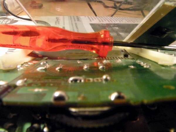
OK, you now have a modified LCD consisting of a front polarized film and two sandwiched pieces of glass with liquid crystal between them. Now to replace your reflective film (and perhaps your rear polarized film too) with a light source! Underneath the glass panel are numerous pointy metal bits sticking out from the PCB. These are legs, or, to put it another way, these metal legs are left over from when the components were soldered onto the printed circuit board. Flip your board over and you'll see what I mean. Those legs correspond to resistors, capacitors, and the like. Anyways, if you leave them like that, they may cause PRESSURE POINTS once you've closed your unit up. The 3mm modules are a bit more prone to this issue, as they're thicker, but you will even see this from time to time on a 1.5mm module if you don't trim them down!
Take a small pair of wire cutters, (alternately, a rotary tool [AKA dremel] or a needle file will also work fine here,) and snip or carefully sand off as much of the excess as you can. Run a finger over those points you just snipped/sanded. Make sure they're not protruding too much!

COMPONENT REMOVAL AND MODULE PLACEMENT
Remove the resistor and zener diode indicated below. Remove the indicator LED as well. Now press in the plastic tab holding in the left side of the plastic housing. Flip your PCB back over again.


Take a pair of wire cutters and snip off the left portion of the plastic housing. Throw this away.

Now, take your SMT module. The newer models (V2) has a noticeable dark gray bar on the left. The older V1 model has a lighter gray bar and longer black and red wires. See below for pictures of the two different models. V1 is on the left, V2 on the right.


RESISTOR PLACEMENT
you have two options here. If you want to turn your backlight on and off independantly of the Game Boy, see the switch photo. If you want your module to go on and off with your Game Boy, see switchless.
Heat up the correct spot on your PCB and poke your resistor leg through.
Switchless:

Switch:

Solder your resistor to the end of the anode (your red wire). Now, solder your cathode to the point that previously held your power indicator LED.


You should be all set. Plug your front PBCs ribbon cable into the rear PCB and power it on. Congratulations, you've backlit your LCD!
Extra tips and tricks
You may want to secure the module now using a bit of hot glue. A bead of glue in the lower left corner usually does the trick nicely.
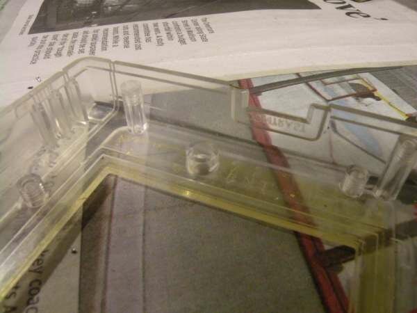
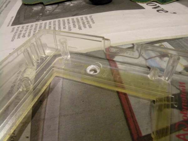
I highly recommend you trim down the plastic near the LED indicator position on the front part of the case. I find what works best is to squeeze this section with a pair of wire cutters and twist instead of cutting into it, if you do it right the whole thing will come off nicely, as seen below.
Once your module is installed, reinsert at least one of the screws for the lower ribbon cable. The one on the left is essential. Look at your LCD and make sure it lines up with the upper portion of the plastic housing. If it doesn't, you can twist the LCD a bit and secure it in place with a small amount of hot glue along the top. If you close up your case without aligning your LCD, it may be off center and will look unprofessional.